

The Truth Table Of Jk Flipflop - is an important concept in the world of electronics and electrical engineering. As the name suggests, it has to do with a specific type of flip-flop known as the JK flip-flop. Flip-flops are electronic components that are used to store a single bit of binary data. They are commonly used in digital circuits to control the flow of information. In this post, we are going to delve deeper into the world of JK flip-flops and understand their various intricacies.
Excitation table for JK flip-flop
A brief introduction
To begin, let us take a look at the excitation table for the JK flip-flop. This table shows us the logic equations for the different inputs and outputs of the flip-flop. It is an essential tool for understanding how the JK flip-flop works. The table indicates that the output of the flip-flop changes based on the current state of its inputs and outputs. Specifically, the output changes only when J=K=1, S=1 and R=0, or when J=K=0, S=0 and R=1. All other combinations leave the output unchanged.

Logic Diagram And Truth Table Of Jk Flip Flop - Wiring Diagram Schemas
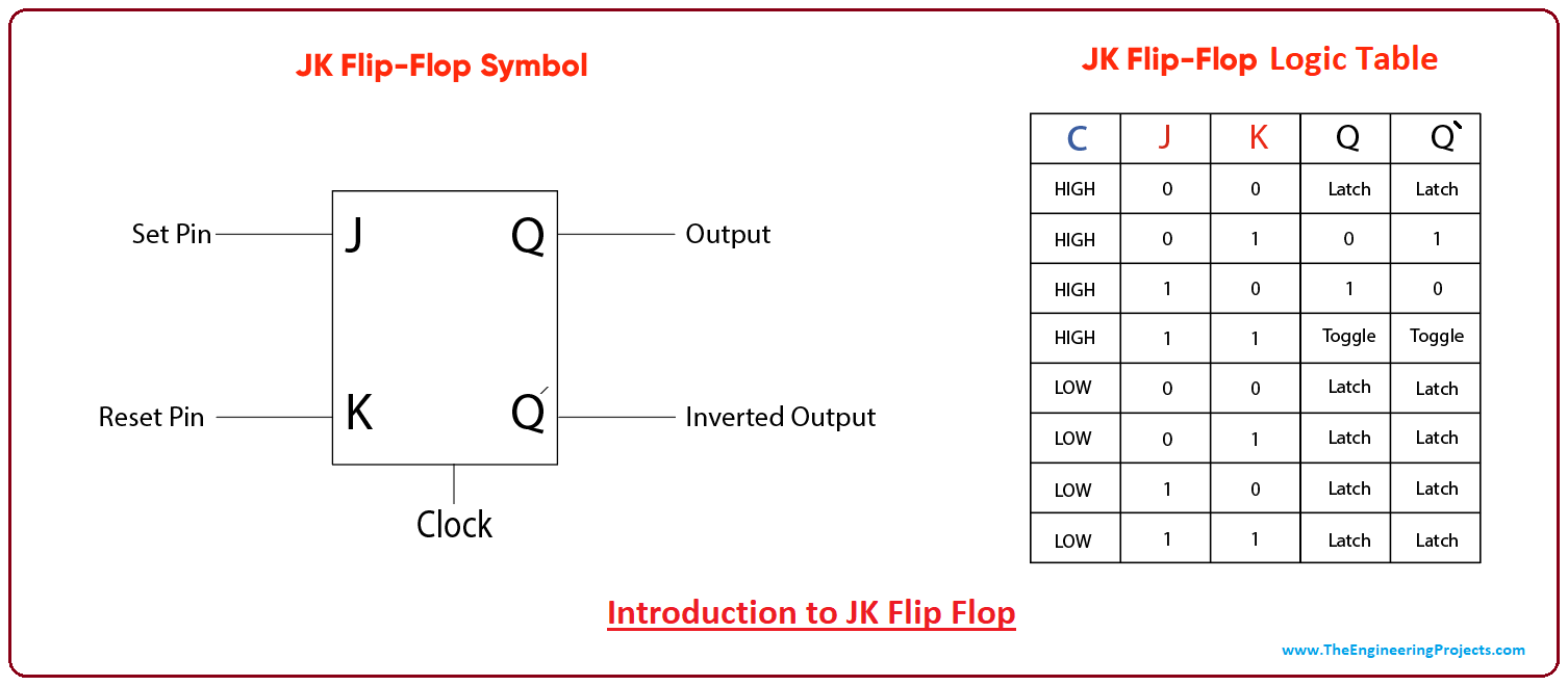
The basics of JK flip-flops
The logic diagram and truth table of the JK flip-flop are also important concepts to understand. The diagram shows us the different inputs and outputs of the flip-flop, and how they are connected. We can see that the output of the flip-flop is dependent on the current state of its inputs, as well as the current state of the flip-flop itself. The truth table, on the other hand, shows us the different combinations of inputs and outputs, and how they relate to each other.
JK Flip Flop Circuit using 74LS73 - Truth Table
The practical application of JK flip-flops
The JK flip-flop is widely used in digital circuits because of its versatility and reliability. One example circuit is shown above using the 74LS73. Its output can be used to control other circuits, making it an essential component in many digital systems. The truth table shown below demonstrates how the flip-flop works in practice.
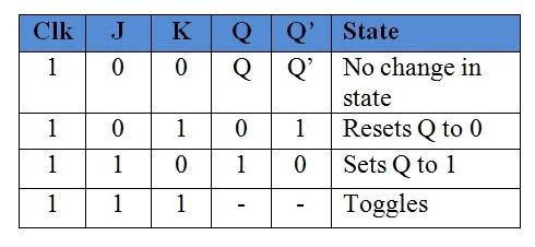
JK flip-flop truth table explained
Advanced concepts
The JK flip-flop truth table can be quite complex, especially when we start looking at the different combinations of inputs and outputs. However, by breaking it down into its individual components, we can start to understand the underlying logic of the flip-flop. For instance, we can see that when both inputs J and K are set to 1, the flip-flop will toggle its output each time there is a clock pulse. This is known as "toggle" mode.

JK flip-flop diagram, excitation, characteristic, Truth table
How to use JK flip-flops in your projects
Now that we have a good understanding of the different components of the JK flip-flop, we can start using this knowledge in our own digital circuits. One of the most common uses of the flip-flop is for sequencing and counting circuits. For example, we can create a digital counter that displays a binary number by using several JK flip-flops connected in series. Another use is in digital memory circuits, where the flip-flop is used to store data for future use.
In conclusion, the JK flip-flop is a powerful and versatile component that is widely used in digital systems. By understanding its intricacies, we can use it to create complex circuits and perform a wide range of digital operations. Whether you are an electrical engineer or hobbyist, the JK flip-flop is an important concept that should be in your tool-kit. We hope this post has provided you with useful insights into this fascinating topic.
Read more articles about Truth Table Of Jk Flipflop